What Is a Container Energy Storage System?
A container energy storage system (ESS) is a fully integrated, modular, and factory-tested electrochemical power plant enclosed within a standardized ISO shipping container. Engineered for heavy industrial and utility infrastructure, it seamlessly synchronizes high-density lithium-ion battery matrices, bi-directional power conversion systems (PCS), multi-tier battery management systems (BMS), and automated intelligent energy management systems (EMS). This complete system features internal environment controllers and multi-hazard fire suppression to optimize commercial battery storage and utility-scale energy storage operations globally.
1. The Macro-Grid Paradigm Shift: Embracing Modular Flexibility
The global power infrastructure is moving through an unprecedented transition away from synchronous centralized power generation toward asynchronous variable renewable energy (VRE). In this highly complex operational ecosystem, the traditional methods of grid balancing are no longer viable. Gas-fired peaker plants are too slow and carbon-intensive to handle the rapid ramps caused by multi-megawatt solar and wind injection. This is where the modern container energy storage system has become the core infrastructure asset for utilities and industrial facility managers worldwide.
By consolidating power electronics and chemical storage into standard 20-foot and 40-foot enclosures, a containerized BESS completely bypasses the traditional civil engineering bottlenecks of on-site construction. Historically, permanent indoor battery rooms required extensive local building permits, specialized HVAC ducting installations, and high labor costs. A pre-engineered energy storage container operates as a standardized asset. It can be factory-commissioned, shipped directly via standard freight channels, and placed onto a concrete pad to begin operation within days. This operational agility allows project developers to respond rapidly to changing local grid dynamics and capture high-tariff windows before market conditions shift.
Furthermore, the utility landscape has evolved. Grid operators no longer view storage as an emergency backup. Instead, it is an active market participant. In modern grids, a high-capacity utility battery storage container provides continuous voltage stabilization, rapid response capacity, and synthetic inertia. This transition from a passive power reserve to an active grid-forming asset represents a profound technological evolution, turning standard battery chemistry into a highly sophisticated asset class for international investors.
2. Advanced Thermodynamic Engineering: The Transition to Active Liquid Cooling
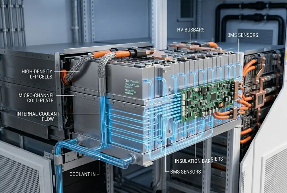
At the heart of every high-capacity lithium battery storage container lies the fundamental challenge of thermal management. Electrochemical systems operate efficiently within a narrow temperature window. When Lithium Iron Phosphate (LFP) cells are subjected to continuous charging and discharging cycles, internal resistance creates significant heat. If this heat is not uniformly dissipated, it results in localized hot spots within the battery modules.
In legacy storage designs, forced-air cooling systems were used to manage internal temperatures. However, air possesses a low specific heat capacity ($C_p \approx 1.005 \text{ kJ/kg}\cdot\text{K}$). In dense arrangements, air cooling naturally creates a thermal gradient across the racks. Cells positioned closest to the intake fans remain cool, while cells located in the center or the rear of the enclosure experience elevated temperatures, sometimes exceeding a variance of 12°C. This delta leads to asymmetrical internal resistance development, accelerated chemical aging, and a phenomenon known as “capacity walking,” where the poor performance of a few hot cells prematurely limits the usable energy capacity of the entire multi-megawatt string.
To address this bottleneck, a modern industrial liquid cooled battery container utilizes a closed-loop hydronic system. A mixture of water and ethylene glycol is circulated through micro-channel cold plates directly in contact with the battery cells. Liquid possesses a heat transfer coefficient orders of magnitude higher than air, allowing the thermal system to maintain a cell-to-cell temperature delta ($\Delta T$) of less than 2°C across the entire container.
This uniform temperature control has a direct impact on the financial metrics of the asset. By eliminating thermal stress, the BMS battery storage system can safely authorize high-current charging without risking accelerated degradation. This expands the system’s longevity from a typical 5,000 cycles under air cooling to more than 9,000 cycles at a standard 80% State of Health (SOH) retention, directly lowering the asset’s total operational depreciation over its lifetime.
3. Electro-Mechanical Architecture: Breaking Down the Core Subsystems
Evaluating a container energy storage system requires a granular understanding of its sub-components. The integration of power electronics, hardware safety, and software logic must be balanced to ensure continuous uptime in demanding outdoor environments.
3.1 Bidirectional Power Conversion Systems (PCS)
The PCS energy storage inverter is the bridge between the DC electrochemical domain of the batteries and the AC domain of the high-voltage electrical grid. Modern PCS units utilize high-frequency Insulated Gate Bipolar Transistors (IGBTs) or Silicon Carbide (SiC) metal-oxide-semiconductor field-effect transistors (MOSFETs) to achieve bidirectional conversion efficiency exceeding 98.5%.
In heavy industrial applications, the PCS must operate in both grid-following and grid-forming modes. In grid-following mode, the inverter tracks the external grid’s voltage vector and injects precise active and reactive power. In grid-forming mode, the PCS behaves as a virtual synchronous machine, establishing an independent local voltage reference and frequency vector. This allows the modular energy storage system to operate autonomously in isolated island scenarios or microgrids during complete external grid blackouts.
3.2 Three-Tier Battery Management Systems (BMS) Architecture
To govern thousands of individual LFP cells safely, a hierarchical, three-tier BMS battery storage network is utilized to process operational data in real-time:
- Tier 1: Battery Module Electronics (BMU): Attached directly to individual cell blocks, the BMU continuously measures cell voltage, surface temperature, and localized internal resistance, executing passive or active cell balancing to ensure uniform charge states.
- Tier 2: Rack Management System (RBMS): Consolidates data from up to 20 individual BMUs. The RBMS monitors total rack voltage, manages the high-voltage DC contactors, and calculates string insulation resistance to prevent ground faults.
- Tier 3: System Management Unit (SBMS): The central communications hub of the container. The SBMS aggregates data from all RBMS units, interfaces with the master EMS battery storage platform via high-speed CANbus or Modbus/TCP, and commands safety shutdowns during over-voltage or thermal anomalies.
3.3 Intelligent Energy Management Systems (EMS)
The master EMS software functions as the primary operational controller of the entire project. It executes optimization algorithms that continuously analyze local grid utility pricing, facility load profiles, and renewable generation data. By deploying artificial intelligence and machine learning models, the EMS can predict upcoming peak demand windows with high accuracy, automatically staging the discharge profile of an industrial energy storage system to minimize demand charges and maximize the returns of your smart energy management strategy.
4. Technology Architecture Comparison: Evaluating Alternatives
When selecting a large-scale power solution, engineers must balance spatial footprints, civil site preparation requirements, and long-term asset scalability. The following matrix contrasts a 2026-spec containerized BESS against legacy stationary designs and diesel-driven peaker alternatives.
| Performance Variable | Containerized BESS (Liquid Cooled) | Traditional Brick-and-Mortar Room | Industrial Diesel Generator Set |
|---|---|---|---|
| Site Footprint Density | Ultra-High (Up to 450 kWh/m³) | Low (Requires extensive clearance aisles) | Medium (Includes external fuel tanks) |
| On-Site Construction Risk | Minimal (Plug-and-play connection) | High (Involves complex masonry & HVAC) | Medium (Requires mechanical alignments) |
| Response Latency | Sub-millisecond (<10ms) | Sub-millisecond (<10ms) | Poor (Requires a 10s to 30s warm-up) |
| Round-Trip Efficiency | High (89% – 93% net system) | Medium (80% – 84% due to HVAC losses) | Low (35% thermal fuel efficiency) |
| Environmental IP Rating | IP54 / NEMA 3R Outdoor Rated | Dependent on building envelope | IP23 to IP54 with specific enclosures |
5. Financial Engineering: Revenue Stacking and Levelized Cost of Storage
When deploying millions of dollars into energy infrastructure, focusing entirely on the initial capital expenditure (CAPEX) per kilowatt-hour is an incomplete strategy. Experienced developers leverage the Levelized Cost of Storage (LCOS) metric to measure asset viability. LCOS calculates the total net cost of every megawatt-hour discharged by the container energy storage system over its full commercial lifecycle, taking into account initial purchase price, operational maintenance expenses, parasitic auxiliary energy consumption, and cell degradation profiles.
To achieve a competitive LCOS, a system must implement “Revenue Stacking.” This technique coordinates multiple operational applications simultaneously through the master EMS software, ensuring the container creates value across different layers of the energy market:
5.1 Demand Charge Management & Peak Shaving
Industrial factories and large commercial properties are heavily penalized by regional utilities via peak demand tariffs. These fees are calculated based on the single highest 15-minute consumption window recorded during the month. A high-power commercial container battery storage solution monitors consumption at the main grid connection point. The moment the factory’s load crosses a pre-set threshold, the system discharges in milliseconds, capping the facility’s peak grid draw and reducing monthly demand charges by up to 35%.
5.2 Real-Time Wholesale Energy Arbitrage
In liberalized energy markets, the rapid expansion of renewable generation has created extreme pricing volatility, often leading to negative electricity prices during mid-day solar peaks. A solar + storage container solution capitalizes on this volatility by drawing power from the grid or localized solar arrays when wholesale prices are near zero. The system stores this energy and discharges it back into the grid during peak evening consumption hours, capturing a high price delta that forms a solid foundation for merchant energy projects.
5.3 Ancillary Services and Grid Stabilization
For large-scale infrastructure deployments, participating in utility ancillary service markets offers lucrative returns. Transmission system operators (TSOs) routinely pay premiums for Fast Frequency Response (FFR) and automated frequency restoration reserves (aFRR). Because a utility scale battery storage container can transition from full-power charge to full-power discharge in less than 50 milliseconds, it can provide sub-second stabilization services that outperform traditional mechanical turbines, unlocking highly stable, multi-year utility contracts.
6. Safety Systems Engineering: Mitigating Thermal Runaway Events
In large-scale energy infrastructure, fire safety is a foundational engineering requirement. If a single lithium-ion cell suffers a severe internal defect, mechanical crushing, or extreme overcharging, it can trigger an uncontrollable exothermic reaction known as thermal runaway. This reaction releases flammable gases—including hydrogen, carbon monoxide, and various vaporized hydrocarbons—which can build up within an enclosed space and pose significant deflagration risks if not managed by proper engineering controls.
To achieve full compliance with global standards like NFPA 855 and UL 9540, a professional container energy storage system must implement a comprehensive, multi-layered safety architecture. This design starts with precise off-gas detection. Specialized monitoring sensors continuously sample air within the battery compartments to detect trace concentrations of hydrogen or carbon monoxide at the single-parts-per-million (ppm) level, identifying cell ventilation long before traditional smoke or thermal sensors register an anomaly.
If off-gassing is detected, the container’s automated safety logic immediately isolations the affected DC string and activates high-velocity deflagration exhaust fans. These fans evacuate the accumulated gases to prevent the internal atmosphere from reaching its Lower Flammable Limit (LFL).
Concurrently, the system utilizes specialized pack-level fire suppression. Rather than flooding the entire container with water or gaseous agents after a flame breaks out, modern systems inject clean extinguishing agents like Novec 1230 or targeted condensed aerosols directly into the specific sealed battery module housing the faulty cell. This rapid insulation absorbs heat and smothers the reaction locally, preventing the thermal event from propagating to adjacent cells or racks, satisfying the strict non-propagation criteria established by the UL 9540A large-scale fire testing protocol.
7. Capacity Configuration Engineering: Selecting the Correct Asset Scale
Selecting the ideal capacity configuration requires balancing immediate performance needs against long-term asset degradation curves. Designing too small results in premature system depletion and grid tariff penalties, while over-specifying capital costs can erode project economics.
| Standard Container Capacity | Typical Application Context | Core Duty-Cycle Configuration | Primary Financial Metric Focus |
|---|---|---|---|
| 215kWh – 500kWh | Small Commercial Properties / EV Fast Chargers | 1C Discharge Rate (High Power Bursts) | Demand Charge Penalty Prevention |
| 1MWh – 2MWh | Medium Manufacturing Plants / Data Centers | 0.5C Discharge Rate (2-Hour Continuity) | Peak Shaving & Co-generation ROI |
| 3.7MWh – 5MWh | Utility-Scale Solar Farms / Substation Buffers | 0.25C Discharge Rate (4-Hour Bulk Shifting) | Wholesale Arbitrage & LCOS Optimization |
When deploying systems in extreme environments, designers must incorporate specific regional correction factors. In tropical climates, such as Southeast Asia, continuous ambient humidity levels exceeding 85% require heavy-duty C5-M marine-grade anti-corrosion coatings and internal desiccant dehumidifiers to protect high-voltage DC terminals from condensation track faults.
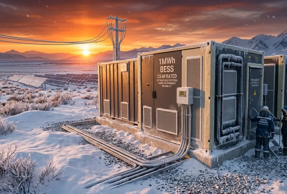
Conversely, for high-altitude or desert deployments in Central Asia, where ambient temperatures fluctuate from -30°C in winter to +45°C in summer, the modular energy storage system must feature multi-layer thermal insulation panels alongside dual-mode liquid thermal loops. These loops can quickly transition from active chilling to active heating to prevent the LFP chemistry from freezing during prolonged idle states.
To address long-term battery degradation, forward-thinking operators rely on modular augmentation. Rather than over-sizing the initial 1MWh container energy storage system price matrix by 30% to account for capacity loss over time, developers can integrate a system engineered for expansion. This allows new battery strings to be hot-swapped into spare internal slots during Year 6 or Year 12 of operation, leveraging future decreases in lithium-ion cell pricing to lower the overall life-cycle cost of the facility.
8. Why Engineering Teams Partner with anengji Power
In the highly competitive landscape of international energy storage, anengji Power distinguishes itself by delivering turnkey, tier-one engineered container solutions optimized for challenging environments. We do not use general third-party sub-assemblies. Every component—from the custom hydronic distribution lines within our liquid cooled battery container arrays to the internal embedded firmware managing our three-tier BMS architecture—is designed and manufactured in-house to guarantee complete system integration.
Our flagship container series features full factory-certified compliance with UL 9540 and NFPA 855 standards, providing global asset managers and financing institutions with the necessary third-party testing documentations to secure fast insurance underwriting and hassle-free grid interconnection approvals.
By combining high-density 314Ah LFP cell chemistry with advanced liquid cooling loops, anengji Power delivers systems that consistently achieve a net round-trip efficiency exceeding 91.5%, providing industrial operators with a reliable, long-term solution to reduce operational costs, stabilize facility power quality, and maximize the return on investment of their energy infrastructure.
9. Frequently Asked Questions Regarding Container BESS
What is the typical operational lifespan of a containerized BESS?
A premium-grade container energy storage system built with advanced LFP chemistry and active liquid cooling provides an operational lifespan of 15 to 20 years. This longevity is highly dependent on system duty-cycles, depth of discharge (DoD), and thermal management precision. Under standard 1C cycling profiles at 80% DoD, the system will comfortably deliver 8,000 to 10,000 operational cycles before the capacity drops to 70% of its initial rating.
How does liquid cooling impact the internal parasitic power consumption?
While active liquid cooling systems require dedicated pumps to circulate coolant, their overall efficiency is significantly higher than traditional air-cooled structures. Air cooling requires high-power fans to move large volumes of air, which can consume up to 10% of the total energy stored in the container. Liquid systems reduce this parasitic load to less than 3.5%, significantly improving the overall round-trip efficiency of the installation.
What is the budgetary breakdown for a 1MWh container energy storage system price?
The turnkey pricing for a 5MWh container BESS varies based on configuration parameters, including the C-rate requirement, cooling method (air vs. liquid), and integrated safety systems. Generally, a fully certified industrial liquid-cooled container ranges from $175,000 to $240,000 USD (Ex-Works), inclusive of integrated PCS, BMS, and fire suppression systems.
Can containerized systems operate completely isolated from the main electrical grid?
Yes. When integrated with advanced bidirectional Grid-Forming (GFM) power conversion systems, an energy storage container can operate in a complete off-grid or islanded configuration. In this scenario, the system functions as a master voltage source, regulating frequency and managing local voltage vectors to support localized microgrids for remote mining operations or industrial industrial facilities.