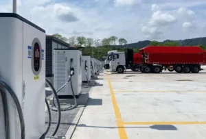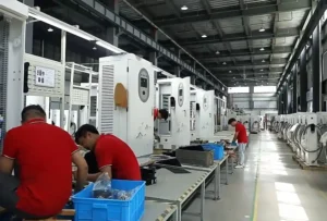
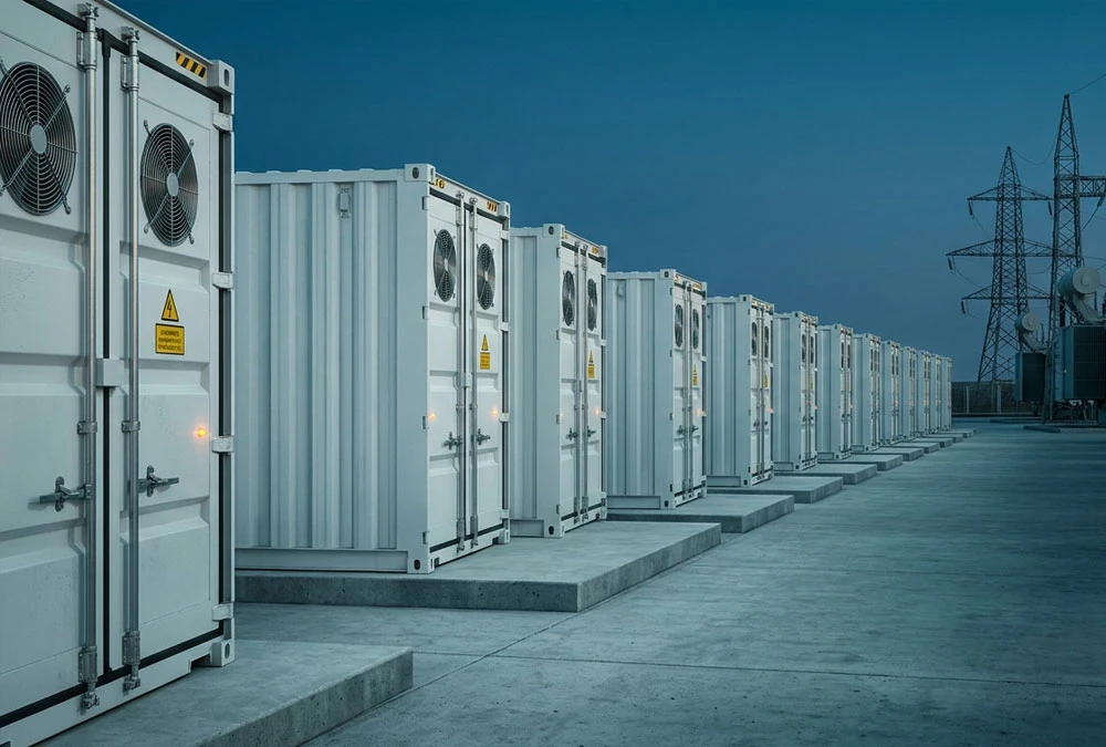
Discover how high-voltage grid scale battery storage systems (BESS) resolve thermal overload, mitigate renewable curtailment, and deliver millisecond frequency response to transform intermittent clean power into bankable, dispatchable energy infrastructure.
The modern power transmission grid is experiencing a fundamental structural shift. For over a century, electrical grids operated on a deterministic model: centralized, dispatchable thermal generators spooled up or down to track predictable consumer demand curves. The rapid influx of variable renewable energy (VRE)—primarily solar photovoltaics and wind turbines—has disrupted this legacy architecture. Intermittent generation introduces critical operational challenges, including the steep ramping rates of the “Duck Curve,” voltage fluctuations, localized transformer overload, and dangerous drops in system inertia.
To maintain grid equilibrium without relying on carbon-intensive natural gas peaker plants, electric utilities, Independent Power Producers (IPPs), and transmission system operators (TSOs) are turning to grid scale battery storage. Operating as massive, multi-megawatt (MW) to gigawatt-hour (GWh) energy reservoirs, utility-scale Battery Energy Storage Systems (BESS) absorb excess power during times of low demand and inject active or reactive power back into transmission nodes in milliseconds, establishing the foundation of a resilient, decarbonized energy future.
1. What Is Grid Scale Battery Storage? Technical Architecture & System Anatomy
A grid scale battery storage system is a high-voltage, utility-grade infrastructure asset engineered to interface directly with transmission (e.g., 69 kV to 500 kV) or primary distribution (11 kV to 35 kV) networks. Unlike residential backup wall-batteries or commercial behind-the-meter (BTM) systems, a grid-scale installation is a multi-layered engineering ecosystem housed inside specialized, weather-proof, IP55/NEMA 3R or NEMA 4X outdoor enclosures.
The Four Core Architectural Pillars of Utility BESS
To operate safely and profitably in wholesale capacity and ancillary service markets, a utility-scale battery plant relies on four seamlessly integrated technology tiers:
Tier 1: Battery Subsystem & Electrochemical Stacks
Consisting of low-degradation Lithium Iron Phosphate (LiFePO4 or LFP) prism cell modules grouped into high-voltage DC racks (typically operating between 1,000V DC and 1,500V DC to minimize conduction losses). Each rack features integrated localized fusing, thermal sensing, and aerosol fire-extinguishing interfaces.
Tier 2: Power Conversion System (PCS) & Grid-Forming Inverters
Bi-directional utility-scale inverters using advanced Insulated Gate Bipolar Transistors (IGBTs) or Silicon Carbide (SiC) semiconductors. Modern PCS units feature Grid-Forming (GFM) inverter control with synthetic inertia capabilities, enabling the storage asset to establish a voltage vector and operate independently of legacy synchronous generators during blackouts.
Tier 3: Multi-Tiered Battery Management System (BMS)
A 3-level hierarchal safety structure (Cell Level → Module Level → Rack/System Level). The BMS continuously monitors individual cell voltages ($\Delta V < 5\text{mV}$ tolerances), temperature gradients, and State of Charge (SOC) while calculating active State of Health (SOH) and controlling passive or active cell balancing.
Tier 4: Plant Energy Management System (EMS) & Utility SCADA Interface
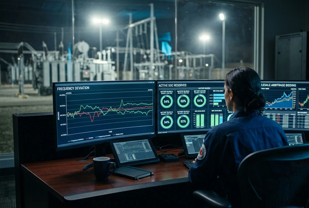
The master control software communicating via DNP3, Modbus TCP, or IEC 61850 protocol to execution nodes. The EMS executes algorithmic market-bidding rules, tracks real-time Locational Marginal Prices (LMP), manages SOC reserves for contract compliance, and responds to Automatic Generation Control (AGC) signals from grid dispatchers.
2. Key Technical Differences: Grid Scale vs. Commercial & Residential BESS
Understanding system scale is crucial for procurement managers, EPC contractors, and project developers. Designing a 100 MW / 400 MWh utility facility involves entirely different engineering parameters, safety clearances, and interconnection requirements compared to Behind-the-Meter (BTM) commercial or residential storage assets.
Engineering Engineering Insight: Why 1500V DC Has Overtaken 1000V Architecture
The utility-scale sector has transitioned almost entirely from 1000V to 1500V DC systems. Increasing nominal DC voltage allows a 50% increase in power throughput per string without raising amperage. This reduces copper cabling cross-sections, lowers $I^2R$ resistive heating losses by roughly 20–30%, optimizes inverter transformer coupling, and yields an estimated 3.5% to 5% reduction in total Balance of System (BOS) CAPEX.
3. Solved Pain Points: How Utility-Scale BESS Protects the Modern Power Grid
A. Mitigating the “Duck Curve” and Eliminating Renewable Curtailment
In regions with high solar penetration (such as California ISO or South Australia), daytime solar overgeneration drops net load demand to historical lows while depressing wholesale electricity spot prices to zero—or negative values. However, as the sun sets, thermal generation must ramp rapidly (often exceeding 15,000 MW within 3 hours) to meet evening peak loads.
Without battery storage, grid operators issue mandatory curtailment orders, disconnecting solar arrays to prevent transmission line thermal overload. A grid scale battery absorbs thousands of megawatt-hours of cheap daytime solar electricity and shifts that power into peak evening hours. This process—known as **Renewable Energy Time-Shifting**—flattens the net load profile and reduces reliance on expensive, high-emission peaking resources.
B. Replacing Synthetic Inertia and Sub-Second Frequency Control (FFR)
Traditional fossil-fuel turbines provide physical rotating inertia, which naturally resists sudden shifts in electrical frequency when a generator trips. As fossil plants retire, power grids lose this protective physical buffer, leading to high rate-of-change-of-frequency (RoCoF) events during unexpected outages.
Grid-scale battery systems equipped with **Fast Frequency Response (FFR)** logic detect frequency deviations ($\Delta f$) instantly. Within 100 to 200 milliseconds of a grid disturbance, modern BESS platforms inject thousands of amperes of active power to stabilize nominal frequency (50 Hz / 60 Hz), providing essential grid stability far faster than mechanical spinning reserves.
C. Transmission and Distribution (T&D) Deferral
Upgrading high-voltage transmission corridors, rebuilding substations, and laying new underground lines can cost millions of dollars per mile and take up to a decade in permitting delays. Strategic placement of a 20 MW / 80 MWh grid battery at a constrained distribution node provides local capacity during peak hours, effectively deferring multi-million-dollar traditional infrastructure overhauls for 5 to 10 years.
4. Advanced Electrochemical Selection: LFP vs. Sodium-Ion vs. Flow Batteries
Selecting the right electrochemical platform directly influences your asset’s 20-year financial performance, safety requirements, and footprint. Below is a data-backed technical comparison of utility-scale storage chemistries:
According to BloombergNEF’s global storage outlook, **Lithium Iron Phosphate (LFP)** accounts for over 90% of new utility-scale energy storage deployments. LFP’s structural stability, complete absence of cobalt or nickel supply constraints, robust cycle life, and high Round-Trip Efficiency make it the standard choice for 2-to-6-hour utility installations.
5. Fire Safety Safety Engineering, Thermal Management & Regulatory Compliance
Safety remains a critical factor in project approval, insurability, and public acceptance for utility BESS installations. Preventing thermal runaway cascade requires a multi-layered, redundant engineering strategy.
Advanced Liquid Cooling vs. Forced Air HVAC Systems
Legacy storage enclosures relied on forced air conditioning, which often resulted in localized hot spots and cell temperature differentials ($\Delta T > 8^\circ\text{C}$). Elevated temperature gradients accelerate cell degradation and trigger non-uniform string aging.
Modern utility BESS designs utilize **Microchannel Cold-Plate Liquid Cooling**. Circulating glycol-water coolant directly along cell plates maintains tight thermal tolerances ($\Delta T \le 2.5^\circ\text{C}$) across the enclosure. Liquid cooling consumes up to 45% less auxiliary power compared to air HVAC units, while extending overall cell calendar life by 20%.
The Four Isolation Control Gates for Thermal Safety
Gate 1: Off-Gas Detection
Early hydrogen and carbon monoxide sensors detect cell venting minutes before thermal runaway occurs, automatically triggering high-voltage relay isolation.
Gate 2: Clean Agent Suppression
Automated gas suppression systems (FK-5-1-12 or Novec 1230) flood the affected enclosure within seconds to extinguish open electrical fires.
Gate 3: Water Injection Interfaces
Dedicated internal pipe manifolds connect directly to external fire department pumper trucks, cooling modules internally if cell temperatures rise.
Gate 4: Explosion Deflagration Venting
Roof-mounted pressure relief panels engineered to NFPA 68 release explosive gas buildup upwards away from personnel.
Global Safety and Regulatory Standards Compliance Checklist
- UL 9540A: Thermal runaway fire propagation testing at the cell, module, unit, and system level. Ensures a fire in one module will not propagate to adjacent racks.
- NFPA 855: Standard for the Installation of Stationary Energy Storage Systems. Governs container spacing (typically 10-foot separation), water supply requirements, and maximum allowed capacity per fire control zone.
- IEEE 1547-2018: Standard for Interconnection and Interoperability of Distributed Energy Resources with Associated Electric Power Systems Interfaces. Enforces active voltage regulation, ride-through capabilities, and anti-islanding protection.
6. Grid Scale Battery Storage Economics: CAPEX, LCOS, and Revenue Stacking
Financial viability in grid storage relies on minimizing the **Levelized Cost of Storage (LCOS)** while maximizing multi-market commercial value streams.
A. Capital Expenditure (CAPEX) Cost Breakdown
Based on financial industry analysis (such as Lazard’s Levelized Cost of Storage reports), total turn-key CAPEX for a standalone 100 MW / 400 MWh 4-hour LFP storage facility typically ranges from $210/kWh to $280/kWh, depending on supply chain dynamics, regional tariffs, and interconnection complexity. Cost allocation breaks down as follows:
- DC Battery Block (50%): LFP cells, modules, rack BMS, liquid cooling systems, and structural enclosure.
- Power Conversion System (18%): Bi-directional grid-forming inverters, power skids, and HVAC auxiliaries.
- Balance of System (17%): Step-up transformers (e.g., 0.69kV to 34.5kV), medium-voltage switchgear, cabling, civil foundations, and site access.
- EPC, Permitting & Interconnection (15%): Engineering design, site studies, utility interconnection queue studies, and land acquisition.
B. Levelized Cost of Storage (LCOS) Formula
LCOS quantifies the discounted lifetime cost per megawatt-hour of discharged electricity, providing a comprehensive metric for comparing energy storage options. The equation incorporates capital costs, operational expenses, charging electricity costs, and end-of-life battery replacement:
C. Revenue Stacking: Maximizing Asset Return on Investment (ROI)
Operating a utility-scale battery as a single-purpose asset rarely yields optimal financial returns. Modern merchant developers use Revenue Stacking strategies, leveraging software algorithms to participate in multiple electricity market opportunities simultaneously:
1. Energy Wholesale Arbitrage (Buy Low, Sell High)
Charging the BESS during off-peak hours or periods of negative pricing, then discharging during evening demand peaks. Software algorithms track day-ahead and real-time market pricing automatically.
2. Ancillary Services (High-Margin Frequency Response)
Participating in Regulation Up / Regulation Down, Spinning Reserves, and Fast Frequency Response (FFR) markets. These services command premium payments from grid operators for continuous fast-response readiness.
3. Resource Adequacy & Capacity Payments
Securing long-term fixed bilateral capacity contracts with regional utilities, guaranteeing fixed monthly $/kW payments for providing guaranteed capacity during critical grid stress days.
7. Modular Hardware Offerings for Utility & Renewable Co-Location
Deploying utility-scale BESS projects requires flexible, pre-engineered, modular energy blocks that lower site installation timelines and streamline system scaling:
Liquid-Cooled 261 kWh / 372 kWh Modular Cabinet
Compact outdoor liquid-cooled battery enclosure engineered for space-constrained feeder substations, distributed solar smoothing, or high-power EV supercharging hubs. Integrated BMS, aerosols, and IP55 protection.
20ft Containerized 3.35 MWh / 3.7 MWh BESS Power Block
Standard ISO 20-foot outdoor container enclosure housing high-density 314Ah LFP cells. Built-in liquid chilling units, localized deflagration vents, and direct DC-bus coupling for high-capacity renewable sites.
5 MWh High-Density 40ft Utility Storage Platform
Turn-key 1500V DC energy storage system optimized for multi-hundred-megawatt independent power producer (IPP) installations. Features centralized liquid cooling, redundant BMS safety channels, and sub-100ms PCS dispatch response times.
Accelerate Your Utility Energy Storage Project
Our engineering team delivers customized utility-scale BESS designs, grid interconnection analysis, fire safety compliance documentation, and financial modeling for global energy storage developments.
Frequently Asked Questions (FAQ)
What is grid scale battery storage?
Grid scale battery storage refers to high-capacity, multi-megawatt energy storage installations connected directly to electricity transmission networks or distribution substations. These assets absorb large volumes of generated power during low demand or high renewable production periods, discharging that electricity during peak demand hours to stabilize regional power grids.
How long do utility-scale battery systems last?
Modern Lithium Iron Phosphate (LiFePO4) utility battery plants are designed for an operational lifespan of 15 to 20 years, offering 6,000 to 8,000 full cycles at 80% Depth of Discharge (DOD). Asset developers typically plan cell augmentation programs around year 10 to restore degraded system capacity back to 100% nominal rating.
What is the levelized cost of battery storage (LCOS)?
Levelized Cost of Storage (LCOS) measures the total cost of storing and discharging one megawatt-hour (MWh) of electricity over the asset’s complete operational life. LCOS incorporates initial capital equipment expenses (CAPEX), ongoing operations and maintenance (OPEX), cost of charging electricity, cycle degradation, and discount rates.
Why is LFP preferred over NMC for grid-scale applications?
Lithium Iron Phosphate (LFP) is preferred over Nickel Manganese Cobalt (NMC) due to its superior thermal stability (exothermic runaway threshold at ~270°C vs ~210°C), lower risk of oxygen release during thermal events, significantly longer operational cycle life, lower cost per kWh, and elimination of cobalt supply chain issues.
What is the difference between grid-following and grid-forming inverters?
Grid-Following (GFL) inverters rely on a strong existing grid voltage waveform (provided by legacy thermal power plants) to sync output phase and frequency. Grid-Forming (GFM) inverters can actively create an independent voltage vector and provide synthetic inertia, allowing the battery system to support islanded microgrids and jumpstart regional networks during widespread blackouts.
What fire safety certifications are required for grid BESS?
Grid BESS deployments typically require comprehensive compliance with UL 9540A (unit-level thermal runaway fire propagation testing), NFPA 855 (fixed energy storage system installation guidelines), IEEE 1547 (grid interconnection interfaces), and localized fire department permits involving deflagration panel venting and internal water deluge interfaces.