Introduction
The first four chargers in a garage are rarely the difficult part. The problem appears when the property owner wants 20, 50 or eventually every parking space to have access—yet the transformer, floor feeders, cable routes and operating rules were never designed for that scale. An EV charging parking garage project can therefore look successful on opening day and become expensive, slow or unfair as utilisation grows.
The decision is not simply “How many 22 kW chargers can we buy?” It is: How much energy must be delivered before each driver leaves, which electrical boundary limits that delivery, and how many connectors must remain practically available? This guide gives parking owners, facilities managers and EPC teams a capacity method, a worked example, solution comparisons and a procurement checklist. It also explains the less visible constraints—phase imbalance, underground communications and occupied-but-idle bays—that often determine whether a garage charging system works after the pilot phase.
The short answer
- Size the system from required kWh and parking time, not from charger nameplate power alone.
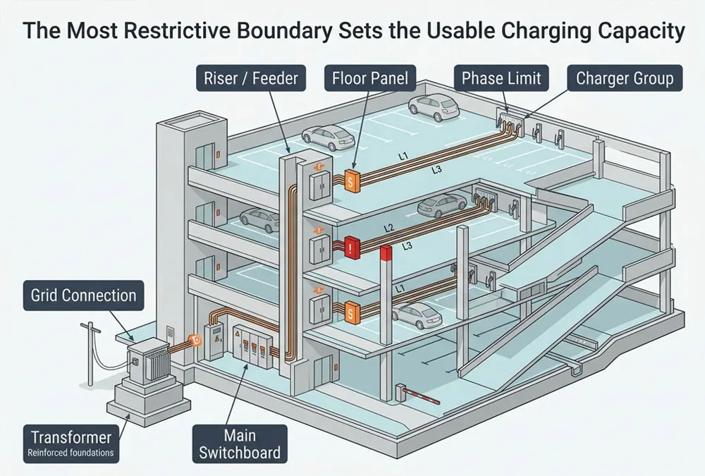
- Check every boundary: grid connection, transformer, switchboard, feeder, phase and charger group.
- Use managed AC charging for broad long-dwell coverage; add DC only where a shorter departure window justifies it.
- Install the future cable routes, panel space and communications backbone before installing every future charger.
- Commission offline behaviour, energy delivery and connector availability—not only electrical safety and charger start-up.
Why Parking Garage EV Charging Fails After the First Few Chargers
A pilot often uses the nearest spare circuits and the easiest bays. Scaling exposes a different project. The next group may be one or two floors away from the electrical room, behind a smaller feeder, or across a fire compartment. A cloud dashboard may show that the whole charging group remains below its limit while one phase or one floor panel is already constrained.
Parking behaviour creates another limit. A commuter may need only 12–18 kWh during an eight-hour stay, but the vehicle can occupy a connector long after charging stops. In that case the garage has enough electrical energy but insufficient usable access. Adding power does not release the blocked bay; more connectors, a rotation policy or parking-system integration may be the better investment.
The design objective should therefore be written as an operating outcome:
Deliver the required kWh by each vehicle’s departure time, while respecting every electrical limit and keeping enough connectors available.
Calculate Garage Charging Capacity Before Choosing Equipment
Begin with the charging task, not a catalogue. For an early energy check:
Required average EV power budget (kW) ≈ total metered charging energy required (kWh) ÷ effective charging window (hours)
The metering boundary matters. If the requirement is energy recorded by the charger, do not add a second conversion-loss factor. If the target is battery-side energy, the designer must apply a separately justified efficiency assumption. The calculation also does not determine the final cable or protection rating; arrival peaks, phase allocation, operating reserve, charger outages and the shortest departure deadlines still require interval modelling and electrical design.
Illustrative 100-space office garage
Assume the busiest credible weekday produces 20 simultaneous charging requests and each vehicle needs 16 kWh during an eight-hour parking window. These are engineering assumptions for explaining the method, not recommended values for every office.
| Planning input | Illustrative value | Calculation | Buyer meaning |
|---|---|---|---|
| Vehicles requiring energy | 20 | — | Establishes the connector and scheduling task |
| Energy required per vehicle | 16 kWh | 20 × 16 kWh | Total metered charging task is 320 kWh |
| Effective window | 8 hours | 320 kWh ÷ 8 h | 40 kW is the idealised average EV budget |
| All 20 vehicles connected under a 60 kW cap | 3 kW average each if shared equally | 60 kW ÷ 20 | The cap appears adequate on average, but early departures and unequal needs still require priority logic |
This example exposes a common purchasing mistake. Twenty 11 kW chargers have 220 kW of combined nameplate power, but the garage may not need 220 kW simultaneously. Conversely, a 40 kW average result does not prove that a 40 kW connection will satisfy every driver. The EPC team should replay actual or surveyed arrival, departure and kWh requirements in time intervals, then test a charger outage and the building’s own peak load.
What official smart-charging guidance demonstrates
The report Standards for EV Smart Charging: A Guide for Local Authorities explains that charge points at one site are not always used simultaneously. Its load-management example connects ten 22 kW charge points—220 kW of aggregate nameplate output—to a 50 kW supply. That supply equals about 23% of the combined nameplate rating; if all ten vehicles drew an equal share at once, the average would be 5 kW each. The guide presents this as an illustration of allocation flexibility, not a universal design ratio. For a garage owner, the lesson is to model real energy deadlines before paying for the sum of every connector’s maximum rating. Read the smart-charging guide.
Use the GARAGE Method to Find the Real Capacity Constraint
A scalable EV charging parking garage design should pass six connected checks. Skipping one can move the bottleneck rather than solve it.
G — Garage operating model
Separate staff, residents, hotel guests, shoppers, fleet vehicles and public users. Record dwell distribution—not only an average—plus required energy, departure deadlines, assigned or shared bays and the cost of a missed charge. Long dwell generally favours broader AC access; short, operationally critical stops may justify selected DC capacity.
A — Available electrical headroom
Review interval building demand and the single-line diagram. Record the grid connection, transformer, main switchboard, each EV feeder, floor panel and per-phase limit. “The building has 150 kW spare” is incomplete when a lower-level feeder has only 40 kW available or one phase reaches its limit first.
R — Routes and readiness
Measure cable distance from the electrical room to every planned bay group. Identify risers, tray capacity, core drilling, structural zones, fire compartments, waterproofing, drainage and impact protection. Installing spare containment and panel space during phase one can be more valuable than installing unused chargers that will age before demand arrives.
A — Allocation and controls
Define whether the system applies a fixed cap, shares power within one charger group, or changes the EV budget from a live building meter. Then define priorities. Equal sharing may be acceptable for overnight residents; fleets or short-stay users may need required-kWh and departure-time logic. The detailed distinction belongs in the existing guide to EV charger load management.
G — Governance and commercial rules
Decide who can start a session, who pays, how energy is measured, whether a parking fee continues after charging, and who resolves a dispute. A technically adequate garage can still disappoint users when the same vehicles occupy the best bays all day. Track connector occupancy and active charging separately; use notifications, a reasonable grace period, reservation rules or idle fees where they match the site.
E — Emergency, accessibility and evidence
Coordinate electrical protection, fire strategy, ventilation, evacuation, emergency isolation, accessible bays and traffic movement with the competent local teams. Require drawings, settings, certificates, test logs and ownership of each corrective action. A charger marked “online” is not evidence that the whole garage system meets the departure-energy target.
Compare Four Solutions to Parking Garage Capacity Constraints
| Solution | Best fit | What it solves | What it cannot solve alone | Buyer consequence |
|---|---|---|---|---|
| More managed AC ports | Long dwell, many users | Expands connector access within a controlled EV budget | Insufficient daily energy or short departure windows | Often the first option to test before upgrading the service |
| Feeder or service upgrade | Energy model still fails after managed charging | Adds genuine electrical capacity at the constrained boundary | Blocked bays, poor placement or weak operating rules | Spend at the actual bottleneck, not automatically at the utility connection |
| Managed AC plus limited DC | Mixed long-stay and priority users | Provides broad access plus a recovery option | Unclear priority, queueing or inadequate site capacity | Avoids assigning DC power and cost to every bay |
| BESS with an energy-management system | A proven peak, tariff or resilience case | Can shift or buffer demand when correctly sized and controlled | Undersized feeders, protection, fire strategy or connector policy | Evaluate only after interval load and charging data establish the duty cycle |
Match AC and DC Charging to How the Garage Operates
The best power level follows parking time and the cost of delay. “Faster” is not automatically more useful when a vehicle remains for eight hours, while low-power AC may be unsuitable for a fleet vehicle that arrives late and must leave soon.
| Garage operation | Likely starting architecture | Key data to validate | Avoid this mistake |
|---|---|---|---|
| Office / employee | Many managed AC ports | Commute energy, arrival peak, shift length, phase balance | Buying high power while too few employees can connect |
| Shopping centre | AC plus selected DC where turnover supports it | Visit-duration distribution, queue, tariff, utilisation | Assuming every visitor wants a near-full battery |
| Hotel / residential | Broad lower-power AC access | Overnight kWh, assigned versus shared bays, billing | Expecting drivers to move vehicles during the night |
| Airport / long-stay | High connector count with scheduled power | Return time, multi-day occupancy, network resilience | Using a small number of fast bays for multi-day parking |
| Fleet / priority bays | Managed AC or mixed AC/DC by departure priority | Route energy, arrival SOC, departure time, outage reserve | Equal sharing when missed departures have unequal consequences |
Three Hidden Constraints That Change the Design
1. A site-level limit may not protect a floor feeder or a single phase
The load-management boundary must match the electrical boundary. If chargers sit behind different meters or panels, the controller needs the correct measurement and authority for each group. During commissioning, increase building load and connect vehicles in the least favourable phase arrangement. Compare the main meter, feeder current, per-phase current, controller command and charger response. A green cloud dashboard is not sufficient evidence.
2. Underground communications need a defined offline state
Concrete decks, ramps and equipment rooms can create cellular and Wi-Fi dead zones. The resulting problem is wider than an unavailable app. If authorisation or the power limit depends on a cloud path, the design must state what happens when the internet, site network, meter or controller fails. Test cached credentials, local power limits, stored transactions, session continuity and reconciliation after recovery. The OCPP procurement guide explains which charger-to-backend workflows should be proven before rollout.
3. Connector occupancy and charging time are different KPIs
A vehicle can remain connected for eight hours but actively draw energy for only three. Monitor both values. If occupancy is high and delivered energy is low, investigate parking policy, full-battery dwell and bay location before increasing the electrical service. If vehicles leave undercharged while connectors are continuously active, the likely constraint is energy, power allocation or dwell time.
European Parking Garage Requirements Must Shape the Expansion Plan
Europe is not one permitting jurisdiction, but EU-level requirements influence how new and renovated buildings should prepare for charging. The recast Energy Performance of Buildings Directive, Directive (EU) 2024/1275, requires Member States to implement provisions for charging points, pre-cabling and ducting. For new non-residential buildings and those undergoing qualifying major renovation with more than five parking spaces, the directive states at least one charging point per five spaces, pre-cabling for at least 50% of spaces and ducting for the remainder. New or qualifying renovated office buildings use a higher benchmark of one point per two spaces. For all non-residential buildings with more than 20 spaces, the directive sets a 1 January 2027 Member-State obligation involving at least one point per ten spaces or ducting for at least 50% of spaces, subject to its conditions and possible postponement provisions.
Those figures make future-ready pathways part of capacity planning, but they are not a substitute for checking national transposition, building type and project date. The same directive also says the relevant recharging points must be capable of smart recharging and calls for pre-cabling and ducting to support simultaneous, efficient use and, where appropriate, load management. Review the official EUR-Lex text and the European Commission implementation guidance.
Covered and underground car parks need a site-specific fire strategy
The Sustainable Transport Forum’s European Commission-led guidance does not reduce fire safety to one product feature. It organises the strategy around five connected areas:
- fire prevention;
- fire detection;
- evacuation;
- control of fire propagation; and
- fire extinguishing.
The guidance also calls for a risk assessment that reflects the building, vehicles and installed charging infrastructure. This supports a project-specific discussion with the fire engineer, authority and insurer; it does not create a single EU installation recipe. Read the covered-parking guidance.
For England, the Office for Zero Emission Vehicles publishes separate interim guidance for new and retrofitted covered car parks. It is intended for operators, designers, risk assessors and owners, and explicitly does not replace existing legal duties. Treat it as an England-specific design input—not a rule for the EU, the wider UK, the United States, Southeast Asia or Central Asia. View the GOV.UK guidance.
AnengJi Power Classes for Long-Stay and Priority Bays
Hardware should follow the operating model. AnengJi’s published range provides AC choices for longer-dwell bays and lower-power DC choices for priority or shorter-stay users. The data below is a shortlisting reference from the current product pages; final ordering still requires the destination connector, exact firmware, control method, certification scope and simultaneous-output configuration.
| Product option | Published electrical data | Potential garage role | Selection check |
|---|---|---|---|
| 7 kW AC Charger | 230 V, single-phase, 32 A | Long-dwell bays and sites where lower per-port power expands access | Available phase capacity and phase distribution across a large group |
| 11 kW AC Charger | 400 V, three-phase, 16 A | Office, hotel and residential parking with multi-hour dwell | Vehicle AC acceptance and managed-group behaviour |
| 22 kW AC Charger | 400 V, three-phase, 32 A | Medium-dwell bays where vehicles and the site can use the higher AC allocation | Do target vehicles accept 22 kW AC, or would the allocation remain unused? |
| 30–40 kW DC Charger | 380 VAC ±15% input; 200–(750)1000 VDC; 0–100/133 A; Ethernet/4G | A compact DC recovery layer for shorter stays or priority users | Voltage/current curve, port split, connector and control integration |
| 60–160 kW DC Charger | 380 VAC ±15% input; 200–(750)1000 VDC; 0–200 A; Ethernet/4G | Higher-turnover public parking or mixed-use priority bays | Available power at target vehicle voltage, dual-session allocation and site capacity |
For most long-dwell garages, compare the number of useful connections before moving up the power scale. A smaller managed allocation across more AC ports may serve more drivers than a few high-power ports. Where a short-stay or operational vehicle cannot receive its required kWh through AC, a limited DC layer becomes a measurable solution rather than a prestige purchase. Use the commercial EV charger buying checklist to compare the remaining equipment and service scope.
Specify and Commission the Whole Garage System
A useful request for quotation should include:
- Electrical boundaries: single-line diagram, transformer, switchboard, feeder, panel and per-phase limits.
- Charging task: user groups, arrival/departure distributions, required kWh and priority rules.
- Physical scope: bay layout, cable routes, containment, penetrations, fire stopping, drainage and impact protection.
- Control topology: meter, current transformers, controller, charger, CSMS, OCPP functions and every failure state.
- Commercial workflow: access, payment, parking integration, idle policy, data ownership and support responsibility.
- Expansion plan: final port target, spare pathways, panel space, communication capacity and trigger for the next phase.
Site acceptance testing should then prove outcomes, not check boxes:
- No service, feeder or per-phase boundary is exceeded during normal and failure tests.
- Priority vehicles receive their required energy by departure in the agreed test scenario.
- The system enters its documented safe limit when the meter, controller, site network or cloud connection is lost.
- Authorisations and transaction data recover correctly after connectivity returns.
- Connector occupancy, active charging time and delivered kWh can be reported separately.
- The operator knows who responds to a charger, network, payment or parking-policy failure.
Parking Garage EV Charging FAQ
How many EV chargers can a parking garage support?
There is no reliable answer from parking-space count alone. An EV charging parking garage can support only the quantity that its energy windows, electrical boundaries and operating model can serve. Calculate required kWh within each parking window, then check the grid connection, transformer, panels, feeders, phases, cable routes and control architecture. The number of physically installed connectors can exceed the number charging at full power when managed charging and user dwell make that arrangement viable.
Can load management avoid an electrical upgrade?
Sometimes. It can use spare capacity more effectively and reduce coincident charging demand. It cannot create enough energy when many vehicles have short deadlines, nor can it repair an undersized downstream feeder, phase imbalance or inadequate protection. Model the busiest credible day before deciding that an upgrade is unnecessary.
Are AC or DC chargers better for a parking garage?
Managed AC usually suits long-stay office, residential, hotel and airport parking because it can spread access across more bays. DC suits shorter visits or priority vehicles that require more energy before departure. Mixed garages may need both, controlled within one site power budget.
Can EV chargers be installed in an underground garage?
They can be installed where the project complies with the applicable electrical, building, fire, accessibility and parking requirements. The design team should assess cable routing, fire compartments, ventilation, drainage, emergency access, communications and vehicle movement for the actual structure.
What happens if the garage loses internet connectivity?
That depends on the specified charger, controller and backend. The procurement documents should define local limits, offline authorisation, active-session behaviour, transaction storage and recovery. These functions should be tested by deliberately disconnecting each communication path during commissioning.
How can a garage stop fully charged vehicles from blocking connectors?
Measure idle occupancy, notify the driver when charging finishes and apply a site-appropriate grace period, reservation rule or idle fee. Where vehicles naturally remain for many hours, installing more lower-power connectors may be more practical than expecting drivers to move them.
Build the Backbone for the Final Garage, Then Install in Phases
A durable EV charging parking garage plan separates infrastructure readiness from charger deployment. Survey the final bay target, reserve routes and panel space, install the measured control boundary, then add chargers as utilisation and operating data justify them. Increase peak power only when the energy model—not a desire for larger nameplates—shows that managed capacity cannot meet departure needs.
AnengJi can review an initial configuration when the project team provides the country, single-line diagram, available capacity by phase, parking-space count, cable-route distances, user groups, dwell windows, required kWh and expansion target. That information supports a useful AC/DC shortlist and a testable control proposal.