In the accelerating global transition to Electric Vehicles (EVs), the deployment of reliable and efficient high-power charging infrastructure is technically contingent upon advanced power electronics and intelligent energy management. This convergence, characterized by near-unity Power Factor Correction (PFC) and the integration of Battery Energy Storage Systems (BESS), fundamentally addresses the challenge of delivering high instantaneous power (e.g., 200 kW) from grid infrastructure with constrained capacity (e.g., 44 kW).
This technical brief details the core principles, semiconductor advancements, and operational architecture that facilitate high-efficiency conversion and power augmentation in DC fast charging systems, critically examining the function of the BESS in balancing power demand and supply for optimal grid stability and charging performance.
1. Power Architecture and the Grid Constraint Challenge
The design of modern DC fast chargers is governed by the need to maximize energy utilization from the AC grid while adhering to strict power quality standards. The core technical challenge is circumventing the utility service limitation by leveraging energy buffering.
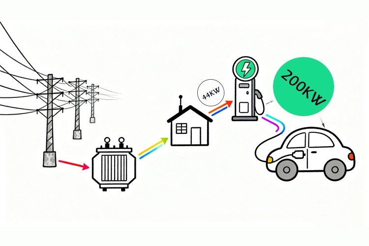
The BESS-Augmentation Principle: Achieving a high power output (P_out) that exceeds the continuous grid input power (P_grid) is accomplished by summing the instantaneous grid power and the power discharged from the BESS (P_BESS), represented by the power balance equation:
P_out = Efficiency (Eta_sys) * (P_grid(t) + P_BESS(t))
where Efficiency (Eta_sys) is the system’s overall conversion efficiency, P_grid(t) is the low, sustained input power (e.g., 44 kW), and P_BESS(t) is the supplemental power drawn from the storage to reach the target charging level (e.g., 200 kW).
2. Core Power Conversion Technologies
The overall system architecture involves three critical stages: AC-DC Rectification with PFC, DC-DC Conversion, and BESS Interface (Bidirectional DC-DC).
2.1 Active Power Factor Correction (PFC) Rectification
The front-end AC-DC stage utilizes active PFC circuits—typically a Boost rectifier topology—to draw a sinusoidal current waveform in phase with the input voltage. This ensures the input power factor (PF) is maintained close to unity (PF $\approx$ 1).
Function: Minimizes Total Harmonic Distortion (THD) of the input current, THD_I, mitigating reactive power and grid infrastructure loading.
Performance Metric: Maintaining PF > 0.99 at full load, which is essential for compliance with IEEE 519 and other international grid codes.
Component Choice: The trend is shifting from Silicon (Si) IGBTs to Wide Bandgap (WBG) semiconductors like Silicon Carbide (SiC) MOSFETs, which enable higher switching frequencies (f_sw > 100 kHz), leading to reduced passive component size (inductors and capacitors) and improved volumetric power density.
2.2 High-Frequency DC-DC Conversion
The high-voltage DC-link output from the PFC stage must be converted and regulated to match the EV battery’s voltage requirements, which can range from 200 V to 920 V (especially for 800V EV platforms).
Topology: Common topologies include Interleaved DC-DC Converters (e.g., phase-shifted full-bridge or multi-phase LLC resonant converters). Interleaving reduces the input/output current ripple and distributes thermal stress across multiple modules, enhancing reliability and efficiency.
Key Advantage: Resonant converters like LLC utilize Soft Switching Techniques (Zero Voltage Switching, ZVS, or Zero Current Switching, ZCS) to eliminate switching losses, achieving peak efficiencies often exceeding 98%.
2.3 Bidirectional DC-DC Converter for BESS Integration
The BESS interface requires a bidirectional DC-DC converter to manage power flow:
Charging Mode (Grid-to-BESS): Allows the BESS to be charged at the sustained low power rate (e.g., 44 kW).
Discharge Mode (BESS-to-EV): Releases stored energy to augment the grid input during the 200 kW fast charge.
Topology: Often a Dual Active Bridge (DAB) converter or a modified boost converter, providing high isolation and high power density, while enabling precise State-of-Charge (SOC) management.
Control Strategy: A sophisticated Energy Management System (EMS) uses predictive algorithms to modulate the BESS power contribution, ensuring the maximum 200 kW is delivered without violating the grid’s power cap.
3. Operational Benefits and System Performance
3.1 Grid Harmonic Mitigation and Demand Management
By utilizing the BESS, the charging station transforms from an instantaneous peak load to a steady, manageable base load. This acts as a localized microgrid element that supports ancillary services.
Peak Shaving: The BESS absorbs load fluctuations, enabling the station to reduce the contractual peak power demand with the utility, directly lowering the operator’s demand charges.
Power Quality: The active PFC front-end ensures low harmonic injection, meeting stringent THD_I limits, which is vital for preventing voltage distortion in weakly supported distribution networks.
3.2 Enhanced Thermal Management and Reliability
The deployment of SiC MOSFETs in high-frequency converters results in lower conduction and switching losses, which translates directly to reduced thermal loads.
Benefit: Enables simpler, smaller liquid cooling systems and improved power density (kW/L), ultimately increasing Mean Time Between Failures (MTBF) and overall system reliability.
4. Anengjienergy’s Integrated Solution
Anengjienergy’s charging platform incorporates these critical technologies into a single Hybrid Energy Solution.
The company’s approach is characterized by:
Modular Architecture: Scalable power modules (60 kW to 1440 kW) utilizing redundant N+1 topology, ensuring high availability (>99.5%).
Advanced Control: Proprietary EMS algorithms that optimize BESS dispatch based on real-time grid conditions and Time-of-Use (ToU) electricity tariffs, maximizing operational efficiency and minimizing LCOE (Levelized Cost of Energy).
WBG Adoption: Implementation of SiC devices in key converter stages to realize maximum conversion efficiency (Efficiency_peak > 98%), directly impacting the final charging power delivered to the EV battery.
5. Conclusion
The ability to deliver 200 kW fast charging power from a 44 kW grid connection is a technical achievement rooted in the intelligent integration of BESS and advanced power electronics. This system’s success is defined by the high power quality delivered by PFC, the high system efficiency (Eta_sys) achieved through soft-switching DC-DC converters, and the instantaneous power buffering provided by the BESS. Anengjienergy’s commitment to this Hybrid Energy Solution positions it as a key provider of grid-compatible, highly efficient, and sustainable charging infrastructure globally.